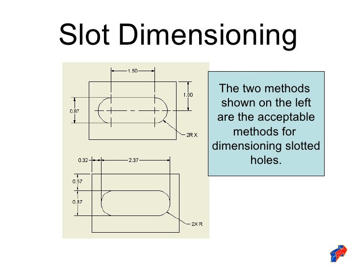

The primary use and description of each characteristic is also shown. The characteristics are grouped together into types of tolerance: form, orientation, location, runout, and location of derived median points. These symbols are placed in the first compartment of a feature control frame and define the type of tolerance that is to be applied to the feature. There are a total of fourteen GD&T characteristics, and the symbols that represent them are shown in the symbol “cheat sheet” below. Symbols or Geometric Characteristics are what most often come to mind when people think about GD&T. Datum features referenced in the end compartments of a feature control frame (see Feature Control Frame), in an order of precedence, will mate the part to the datum reference frame. In defining a part, an engineer will identify the datum features on a part that are most important to the functional requirements of the design-usually the features that mount the part in the assembly. The illustrations below are provided to emphasize that Datums (left) are theoretical (perfect) and datum features (right) are real (imperfect). Datum features are the actual, physical features (holes, faces, slots, etc.) on the part. Datums are points, axes (lines), and planes, or some combination of these components, that make up the DRF. There’s an important distinction between datums and datum features. Parts are mated to the DRF so measurements, processing, and calculations can be made. In order to design, manufacture, and verify parts, the necessary DOF must be constrained. The DRF is the skeleton of the geometric system-it’s the frame of reference to which all referenced geometric specifications are related and the origin of all dimensions and geometric specifications related to it.Ī DRF establishes Six Degrees of Freedom (DOF), three translational and three rotational. It’s arguably the most important concept in GD&T. The Datum Reference Frame (DRF) in design engineering is a three-dimensional Cartesian coordinate system. Tight tolerances are sometimes necessary, but it’s important to keep them in perspective. Small tolerances can increase cost in the manufacturing, inspection, and tooling of parts. The engineer or designer should strive to keep tolerances as large as possible while preserving the function of the part. However, just because you can hold tolerances smaller than a human hair doesn’t mean you need to.

005 inch are expected and achieved from today’s CNC mills. To provide some context, let’s consider an average human hair, which is around. In order to understand geometric tolerancing, it helps to think of parts as having varying degrees of imperfection. These variations (imperfections) are allowed within the tolerance limits (constraints) placed on the parts. When you look at machined parts, they look flat and straight, but if you were to view the parts with calipers, you would find that there are imperfections all over the parts. It’s important to keep tolerances on engineering drawings in perspective, so I think of tolerances like bacteria-like bacteria, they’re not visible to the naked eye, but we know they’re there. Tolerances are an allowable amount of variation. Tolerances are like Bacteria: Small, but Powerful If you want to go even more in-depth into this topic, check out our on-demand webinar on Conveying Design Intent with GD&T. There is a lot to learn when it comes to mastering GD&T, so this post will serve as a launching point to help you understand the most important GD&T concepts, including:
#STANDARD DIMENSIONING PRACTICES HOW TO#
Geometric Dimensioning and Tolerancing (GD&T) is a language of symbols and standards designed and used by engineers and manufacturers to describe a product and facilitate communication between entities working together to produce something.īy deepening your knowledge around how to create a well structured GD&T, you will improve communication with your machine shop and ensure everyone involved is speaking the same language.


 0 kommentar(er)
